The voltage entering the down-hole system is usually 100VDC, but it can range from 80VDC to 120VDC. To minimize interference with the telemetry signals, a filtering circuit is used. The specifications are: Output voltage: 12V DC with a tolerance of ±0.1V, Maximum current: 250mA, Voltage ripple: 100mV peak-to-peak.
To apply power the tool, the power supply goes through an unstable transition zone between 10 to 75 volts, where currents of 150 to 250 mA can appear, depending on the load connected at the VOUT (12V) output. However, once it passes into the stable zone, the current will be much lower, reaching up to 100V, with a current of 12mA without load at the 12V output or 32mA with load at the output. That's why the values in Fig. 8 for current and voltage at 130V are for protection. If the operator accidentally exceeds this voltage (130V), the line is immediately disabled to protect the power supply.
A high-efficiency step-down DC/DC regulator with an internal power switch draws a typical DC supply current of decimas of μA while maintaining a regulated output voltage even when there is no load.
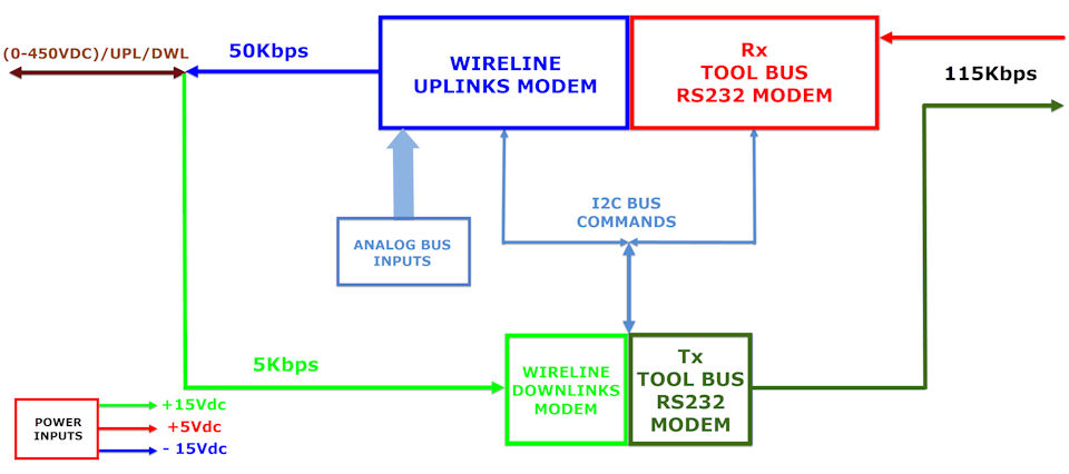
The power supply provides one output of 12VDC with a maximum current of 0.2A to the customer and is designed to operate efficiently at high temperatures. There are three regulators: +15VDC at 60mA, -15VDC at 60mA, and +5VDC at 100mA, to supply power to the telemetry system. The power supply has protection to prevent incorrect polarity at the input.
The Cable Head Voltage is 100V (LINE), and a sample signal (HV_S) is taken at 1VDC. Similarly, the Tool Power Bus Voltage is 12VDC, and its sample signal (LV_S) is at 1.2VDC. These sampled signals are sent to the telemetry board.
The entire system operates within a maximum temperature limit of 177°C for one hour.